What Technicians need to know about on car testing of CAM angle position sensors and related circuitry.
Faulty CAM position sensors may affect various engine operating systems in many ways. In many cases, a no start condition may result from a faulty CAM sensor or related wiring as the ignition system is affected. Other systems utilise the cam sensor signal for sequential injector timing and will allow the engine to run with the CAM sensor disconnected without sequential programming.
Typically: VS-VY 3.8ltr Commodore systems will allow engine to run with single CAM sensor disconnected.

As mentioned in the previous CAM article, there may be singular or multiple CAM sensors utilised by the PCM to monitor the position of the camshaft/s (therefore engine valves). These may be inductive or digital signal type units.
Fault codes assisting in specific diagnosis: (all types of CAM sensors)
In many cases a specific fault code may assist the technician in determining if a CAM sensor signal area of fault is generally created by a mechanical or electrical condition.
Typically:
Logged fault codes P0340 (camshaft position sensor circuit malfunction) and P0341 (camshaft position circuit range/performance) may be the result of both mechanical (camshaft, timing belt/chain) or CAM electrical circuit condition.
Logged fault code P0342 (camshaft position circuit high) is usually caused by faulty CAM electrical circuit conditions.
Note: Ford specific fault code P1000 (OBD11 monitor testing not complete) may be logged when fault codes have recently been cleared and the PCM has not completed a self-diagnostic cycle of all readiness monitors. This code will give no assistance to the technician until the cycles have completed allowing for a suitable fault code to be logged if conditions demand.
Typical vehicle symptoms with faults in CAM sensor system may be:
- Engine hard to start or a no start condition
- Lack of power
- Misfire or rough engine running condition.
When a cam sensor signal or related fault code is logged, the technician must determine the cause of fault. This may be one of the following system areas:
- Movement/phasing (Is there timed rotation?)
- Sensor (Is the sensor faulty?)
- Wiring (open or ground/short circuit)
- PCM (processing signal correctly or CAM sensor power supply and ground if applicable.
Determine if “Inductive type CAM sensor” is functioning.
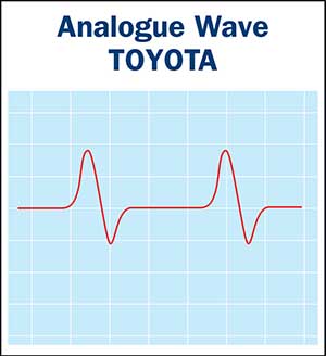
Connecting a suitable oscilloscope to the Cam sensor terminals will quickly allow the technician to monitor any CAM sensor signal.
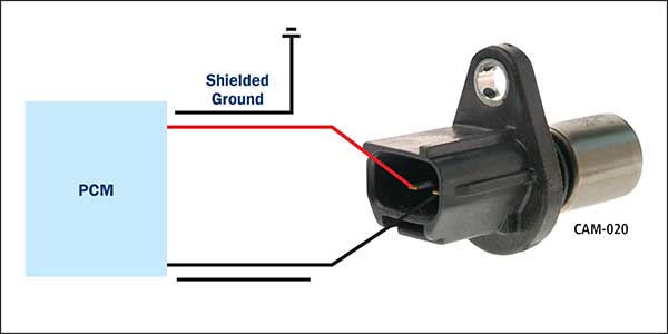
Typical Toyota type CAM sensor and simplified circuit.

A “no signal” condition requires a few simple tests to determine area of fault.
- Disconnecting the harness plug and checking for sensor winding resistance with an Ohm meter will quickly monitor for sensor open or shorted circuit conditions. Typical sensor resistance: Approx. 1100 Ohms @ 30 Deg C.
Note: This type of sensor does not require a power supply to create an AC wave signal.

Functionality test:
Connecting the oscilloscope directly to the sensor with harness disconnected and engine cranking should result in a visible output signal. (Ensure rotation is occurring and is not a factor).
- A “no signal” result will quickly rule out any wiring or PCM causes (replacing the CAM sensor should correct this condition.)
- If a suitable signal is evident using an oscilloscope with the harness disconnected, but is lost when harness is connected, further tests are required at the harness or PCM to determine if a ground to earth is causing the condition.
Testing Hall sensor type CAM sensor for functionality.
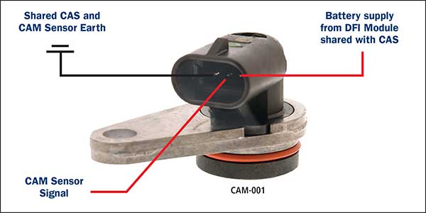
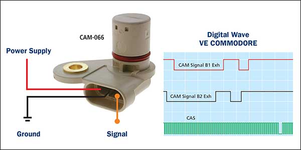
As mentioned in the previous article, unlike the inductive cam sensors, the HALL type sensors require a power supply to function and create a square wave signal.

Testing for a suitable power supply and ground is required prior to condemning a cam sensor for an incorrect HALL signal. Like the inductive type CAM sensor, the wiring harness must be tested for open and short circuits If a no signal is evident prior to renewing the sensor.

