Exhaust Gas Temperature Sensors (EGT)
What Technicians need to know before working on a vehicle fitted with EGT sensors.
- Purpose and identifying the correct sensor by the location on the exhaust.
- Sensor types and operations
- Effects on the vehicle when the sensors fails
- Testing procedures with common test equipment
- Precautions when purchasing new units.
The number of Exhaust gas temperature sensors may vary on vehicles depending on the systems used. They are utilized in both Diesel and Petrol engines – Turbo and non-Turbo. The purpose of the EGT sensors is to monitor exhaust gas temperatures (at various locations on the exhaust) as an electrical voltage signal and sent to the ECU to allow for controlling varying engine conditions to reduce emissions and component protection.
Petrol Engines
Primarily to protect the turbocharger and catalytic converter from thermal overload. (overheating) The PCM will alter timing, fuel mixtures and boost pressure to lower the temperatures. (results in loss of power) Also used for control and protection from overheating of NOx reduction systems.
Diesel engines
The function varies slightly for Diesel engines. The temperature of the DPF (Diesel Particulate Filter) is monitored, not so much for heat overload but to establish that the temperature required for regeneration (self-cleaning) of the DPF has been achieved. Also used for control and protection from overheating of SCR (selective catalyst reduction) or LNT (lean NOx trap) and other NOx Absorbers. Certain EGR systems are now equipped with temperature sensors for EGR Diagnosis (OBD). Are Compact and have lower Maximum temp measurement. (400Deg C).
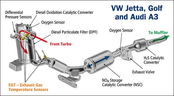
Typical EGT sensor locations
Other models may have many more sensors downstream for more monitoring
Identifying the EGT sensor that requires testing and/or replacing can be a little confusing when the vehicle Is fitted with multiple units. The OBD 11 diagnostic system uses a listing similar to the O2 sensor identification.
A typical diagnostic fault code listed on a scanner may be:
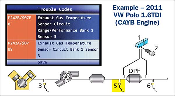
There are three EGT sensors fitted to this vehicle

Part 5 shown above was replaced and vehicle fault corrected. Disconnecting individual connectors and checking diagnostic codes may assist in identification. Note: It is important that the correct part is fitted in the correct exhaust position.
Types of EGT sensors.
There are generally two variations of these sensors used on vehicles that monitor Temperatures up to approx..1000 Deg C
- PTC (positive temperature coefficient) Resistance increases with heat.
Monitoring temperatures for typical applications: Turbocharger, Three-way catalyst, DPF, SCR (selective catalyst reduction), NAC (NOx Absorber catalyst.) and DOC (Diesel oxidation Catalyst.)
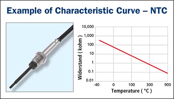
- NTC (negative temperature coefficient) Resistance decreases with heat.
Monitoring temperatures for typical applications: Diesel Turbocharger, DOC, DPF, SCR and NAC.
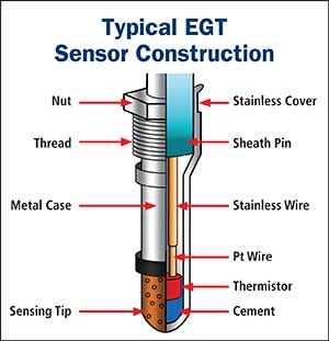
Typical EGT sensor construction
Effects on the vehicle when the sensor fails
A sensor over time can drift out of tolerance limits causing over fuelling issues during Regeneration, due to the process being prolonged. This sensor deterioration may occur over a period.
PTC sensors may continue to relay misinformation to the ECU without setting or delaying a diagnostic trouble code. This may cause the DPF to regenerate outside of its permitted temperature range. In many cases, a DPF has been incorrectly diagnosed as a fault where it has been caused by a faulty EGT sensor.
A typical sensor fitted to Captiva/Cruze Diesel.
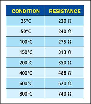
Disconnect and measure the resistance between the two terminals of the Exhaust Temperature Sensor. Compare the readings with the specifications.
NTC sensors are generally designed with 2 wires bonded to a ceramic cell. Over time, an open circuit may be created and resulting in a fault code being logged. This is generally a straight forward fix and repair.
Other causes of failure and test procedure
- Physical damage.
- These sensors may be damaged during exhaust replacement procedures and recommended to be replaced simultaneously with any DPF or other major exhaust component fitted with an EGT sensor.
- Severe vibration may cause the internal component or wire connection damage.
- Excessive prolonged temperature (over 900 Deg) may cause Thermistor element failure.
- Bending the sensor wires excessively. The sensor is to be refitted at the correct angle to prevent stretching and over bending.
- Contamination from oil, antifreeze and poor-quality fuel.
Testing sensors
- An Ohm-meter can be used to quickly identify:
- The resistance value at a specific temperature
- If the internal circuit is a damaged open circuit
- A suitable scanner can of course monitor temperature readings during on-road testing.
- Ensure the correct sensor is fitted to the correct location as they are designed to monitor a specific temperature range depending on the heat created at that location.
- Ensure wiring harness and connectors are intact.