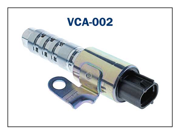
Variable Camshaft Actuators (VCA) Oil control Valves
What a Technician needs to know when working on or diagnosing faults on a Variable Valve Timing (VVT) system.
Brief description of VVT system.
The variable valve timing system is now commonly fitted by most vehicle manufacturers to advance and retard the camshaft in relation to the crankshaft position within the cylinder.
Early VVT systems were utilized to increase engine performance.
Later (more advanced) Cam – Changing and Cam – Phasing VVT systems are utilized to increase Torque, Power, Efficiency and Idle performance throughout the total RPM range.
A typical advanced system is the Toyota VVTL-i with continuous cam-phasing VVT and 2 stage variable valve lift plus valve opening duration applied to both intake and exhaust valves.
A typical simple VVT valve cycle.
The BMW (VVT) Vanos system (Variable Nockenwellen Steuerung) at lower engine speeds, opens the valves later during the intake stroke. This increases the vacuum and scavenging effect which improves idle quality and acceleration from a stationary condition. As the engine RPM increases, the valves are opened earlier to enhance Torque.
n the E46 3-series, the Double-Vanos shifts the intake and exhaust camshaft within a range of 40° and 25° respectively.
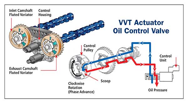
How does the VVT actuator oil control valve affect the VVT system?
The VVT system generally utilizes oil pressure as the internal force for the actuator to change the Camshaft phasing. The flow control of the oil pressure is performed by the VVT actuator control valve that is operated by a pulse width modulated signal from the PCM. The control valve integrates a solenoid and spool valve that allows engine oil to be directed to various paths.
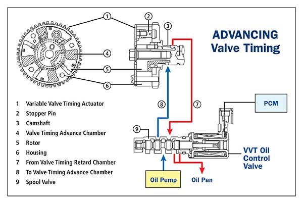
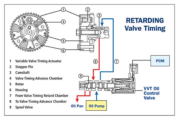
A typical VVT hydraulic circuit schematic.
Typical VVT faults and causes that affect its operation.
Being a mechanical/hydraulic system that is controlled by electronics, there are a few areas of concern if the system is not maintained correctly.
- When the engine oil is contaminated due to extended service intervals or incorrect engine oil viscosity used during an oil service, the VVT system may create a sluggish or seized VVT actuator that can result in poor engine performance and even a no start condition.
- Excess contamination may generally cause the spool valve in the VVT actuator control valve to jam and create an excessive advanced or retarded camshaft condition.
- Failed electrical circuits will cause the actuator to remain in the retarded or advanced position that would depend on the spool valve position in the VVT oil control valve.
- VVT Actuator internal gears and seals may wear over time and cause incorrect VVT operation.
- Low engine oil pressure that can cause incorrect VVT operation and misdiagnosis.
- Incorrect valve timing due to wear in the drive chain/belt or after drive chain /belt replacement.
Note: It is important to investigate any Service Information Bulletins that relate to the VVT system when a malfunction in the system occurs. A malfunction in the VVT system may cause the “Service Engine Soon” (MIL) light to illuminate and multiple fault codes logged in conjunction with loss of engine power and possible rattling sounds.
Oil service schedules need to be adhered to as delaying service intervals is the main factor for VVT failure due to oil contamination and mechanical wear.
Testing the Oil Control Valve.
If the oil control valve is suspected of being faulty, checking the electrical resistance of the coil windings is a simple task.
Typical resistance readings for KIA vehicle VVT valves at 20 Deg C are:
- Denso - 6.9 to 7.9 Ohms
- Delphi - 6.7 to 7.7 Ohms
- Siemens - 6.8 to 8.0 Ohms
If the resistance is within specs, the movement of the spool valve may be inhibited by internal foreign objects. Movement of the spool valve may be checked by powering the 2 terminals of the unit and it is recommended to renew the valve if it is suspect.
On car testing of the VVT.
Utilizing a suitable scanner and a suitable oscilloscope. Checking Camshaft and Crankshaft position sensor signals as well as PWM signals can assist the Technician with VVT operational diagnosis.
Typical VVT vehicle system identification.
VVT: Chrysler, GM, Proton, Suzuki, Isuzu, VAG group, Toyota
VVTi : Toyota, Lexus
AVCS: Subaru
AVLS: Subaru
CPS: Proton
CVVT: Hyundai, KIA
DCVCP: General Motors
DVVT: Daihatsu
MIVEC: Mitsubishi
MultiAir: Fiat
N-VCT: Nissan
S-VT: Mazda
Ti-VCT: Ford
VANOS: BMW
ValveTronic: BMW (also adjusts valve lift)
VarioCam: Porsche
VTEC: Honda
i-VTEC: Honda
VTi : Citroen
VVC : MG, Rover
ValveLift: Audi
VVEL: Nissan, Infinity
CamTronics: Mercedes