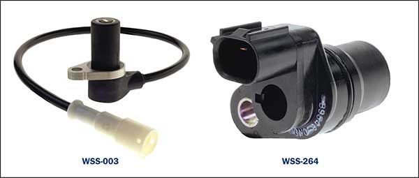
Wheel Speed Sensors (WSS)
What Technicians need to know about the operation of the active wheel speed sensors (WSS) and the operational circuitry to assist in the related diagnosis and testing process on the vehicle.
Even though the operational principals of the Passive and Active type wheel speed sensors have been briefly dealt with during the previous WSS article, troubleshooting both these types can be confusing when it comes to differentiating between the passive and active type units as in many cases they cannot always be distinguished by appearance.
Typically:
PASSIVE SENSOR generally requires 2 wires/terminals on a wired sensor or 2 terminals on a sensor without a cable and does not require an external power source for an output signal.
ACTIVE SENSOR may also be manufactured with a 2 wire/terminal on a Wired sensor or 2 terminals on a sensor without a cable. A variation to the 2 terminal Active sensors is the 3 terminal units.
Why 2 or 3 wires for Active Sensors?
There are generally 2 types of Active WSS used on current vehicles.
- Hall Sensor type WSS (with 2 or 3 Terminals).
- Magneto – Resistive type WSS.
The Hall Sensor type design may require either 2 or 3 terminals for its operation.
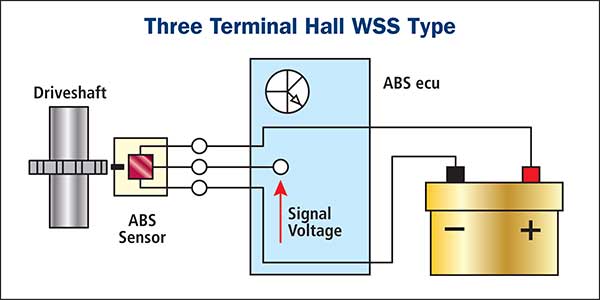
3 Terminal Hall WSS type:
This type has a simple power supply and signal wire with the signal voltage directed to the ABS module. A toothed gear results in a square wave due to the high or low signal voltage. A ground is also required on this type.
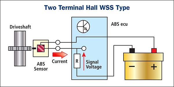
2 Terminal Hall WSS type:
This current regulating type WSS has a 12V power supply wire but no direct ground. The sensor ground is also the signal wire. The amount of current is varied by the sensor when a tooth is passing the sensor. This current through the resistor inside the ABS nodule will produce a voltage related to the ground that resembles the square wave signal of the 3 wire Hall WSS.
Magneto-resistive sensor:
These WSS types utilise an encoder ring similar in appearance to the ring used on Hall sensor WSS however, the construction varies with magnetic arc segments which cause a clear change in resistance when passing the sensor. This enables the ABS control unit to determine the wheels rotational direction. These units are generally known as a more precise unit and less affected by air gap variations.
Note:
Generally, sensor specifications distributed by the respective vehicle manufacturer is necessary to ensure correct signal and vehicle operation. A quick, commonly used identification procedure used by the trade to prevent Identification confusion between Passive and Active WSS is the vast variation of the resistance values between the types.
The Passive type unit windings resistance is a straightforward procedure that can be useful for some simple tests. (open circuit, short circuit and grounded circuit).
Typical Passive type WSS windings specifications.
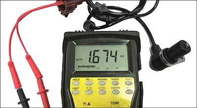
The active type unit resistance is mainly used to identify an active type WSS unit due to the high resistance value compared to the passive type.
Typical Active type WSS specifications.
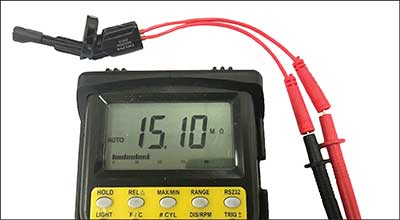
This high resistance value can vary dramatically depending on the type of Active WSS being measured.
Example – Peugeot 308 (also caused on many more makes). A typical fault that can be easily prevented with when working on these systems.
Replacing a rear disk rotor on a vehicle with an integrated bearing and ABS ring may cause a condition where the sensor comes in contact with the new disk rotor- ABS ring and cause physical damage to both.
The cause is generally preventable if the technician is aware that due to corrosion build up under the WSS mounting point, the sensor is now positioned so it comes into contact with the ABS ring. This will cause damage to both the sensor and the ABS ring. Note: Always ensure WSS mounting surfaces are clean and clear of any damage on all vehicles prior to reassembly and the air gaps are suitable.
Be aware:
A test light is not suitable for testing the power supply to the Active type WSS. A test light causes a condition where the ABS module may suspect a possible short to ground that results in the module switching off the supply voltage to the sensor. This is to protect the internal circuits of the processor and the power supply will be resumed only after the Ignition key has been cycled (OFF and ON). Failure to cycle the key may cause misdiagnosis where the ABS module is incorrectly blamed for the cause.
Suitable scanners and specific test equipment are recommended for testing with a suitable oscilloscope also useful for monitoring output signals.